Questions and Answers about Wire Electric Discharge Machining [EDM]
How to set the setting cutting conditions ?
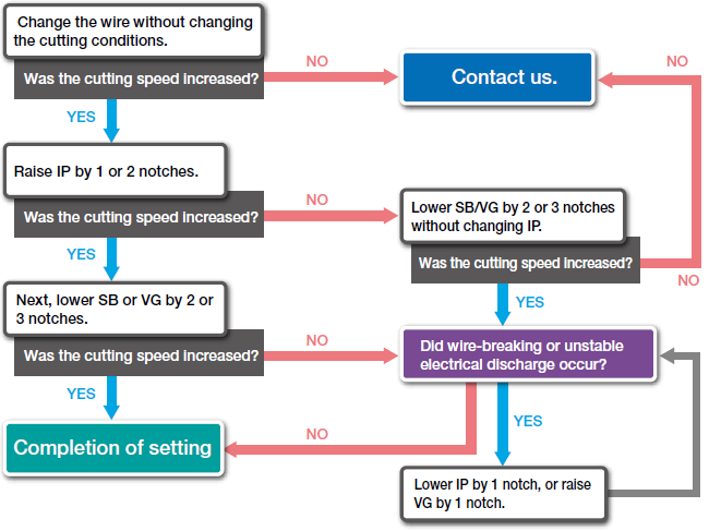
Setting cutting conditions (to increase cutting speed)
(Example) Tuning of Mitsubishi W-EDM machine
Parameters for W-EDM machines of respective manufacturers
| W-EDM machine makers | Discharge energy setting | Off-time setting |
|---|---|---|
| GF Machining Solutions (formerly Agie) | P, T | TD |
| GF Machining Solutions (formerly Charmilles) | A, IAL | B, Aj |
| Seibu | I | OFF |
| Sodick | IP, ON | MA, OFF |
| Fanuc | VM, ON | OFF |
| Makino | Peak current, ON | OFF |
| Mitsubishi | IP | SB, OFF |
Reference: How much the electrical discharge energy can be raised depends on the material thickness.
Superior cutting conditions may be achieved by changing the settings according to the material thickness described below.
| Material thickness | Setting point |
|---|---|
| 20mm or less | - Basically, lesser electrical discharge power is required for thinner workpiece. - A significant increase in speed is not allowed with thinner plates, for which acceleration is limited to being low. - The amount of discharging energy allowed to increase for material with a thickness of 10 mm or less is also small. |
| 20-60 mm | - If the condition of a high-pressure jet stream is good, the machining efficiency will be improved. - For cutting a flat plate, place the nozzle as closely to the plate as possible. - A further increase in discharge energy is possible, given the better discharge of cutting sludge. |
| 60mm or more | - Generally, more wire is consumed and susceptible to breaking more with a thicker plate. - The cutting speed may be increased by raising the wire speed. - Significant changes in conditions are possible, as the EDM wire shows a significant difference from brass wire in this range of thickness. |
Note: As an optimal setting point varies depending on actual cutting conditions and other factors, please review the above-mentioned items so as to match the settings regarding your specific situation.
Please contact us if you have any questions.
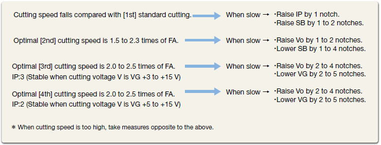
How to change the optimization of cutting conditions?
Optimization of cutting conditions (Example) In case of an W-EDM machine manufactured by Mitsubishi
Case of rough cutting (1st cut)
How to change cutting conditions
(In case of cutting AISI D2, 60 t with φ0.2 wire *For a reference only. [AE: 21 notches, SE: 1 notch used])
1. In case of each workpiece
| Standard value | Adjustment value | |||||||||
|---|---|---|---|---|---|---|---|---|---|---|
| Types of material | AISI D2 DIN 1.2363 |
AISI P25 DIN 1.2330 | AISI 1045 DIN C45 | Stainless steel | Aluminum | Copper | Tungsten carbide copper tungsten |
Graphite | ||
| Voltage switching |
Vo | (Notch) | 12 | 0 | 0 | 0 | 0 | 0 | 0 | +4 |
| Cutting setting |
IP | (Notch) | 9 | 0 | -1 | 0 | 0 | -1 | -1 | -2 |
| Off-time | OFF | (Notch) | 1 | 0 | 0 | 0 | 0 | 0 | 0 | 0 |
| Stabilizer A | SA | (Notch) | 3 | 0 | 0 | 0 | 0 | 0 | 0 | -2 |
| Stabilizer B | SB | (Notch) | 10 | +2 | +2 | +2 | +3 | 0 | 0 | +4 |
| Wire tension | WT | (Notch) | 8 | 0 | 0 | 0 | 0 | 0 | 0 | -1 |
| Average cutting voltage |
VG | (V) | 39 | 0 | 0 | +2 | 0 | +8 | +5 | +15 |
| Actual cutting speed |
FA | (%) | 100 | 90 | 85 | 85 | 200 | 85 | 50 | 40 |
2. In case of each cutting purpose
| Standard value | Correction value | |||||||||
|---|---|---|---|---|---|---|---|---|---|---|
| Types of material | AISI D2 DIN 1.2363 |
Either nozzle separated |
Both nozzle separated |
Stepped workpiece |
Taper 3 degrees |
Taper 5 degrees |
Taper 10 degrees |
Taper 15 degrees |
||
| Voltage switching |
Vo | (Notch) | 12 | 0 | 0 | 0 | 0 | 0 | 0 | 0 |
| Cutting setting | IP | (Notch) | 9 | -1 | -1 | -2 | 0 | 0 | -2 | -2 |
| Off-time | OFF | (Notch) | 1 | 0 | 0 | 0 | 0 | 0 | 0 | 0 |
| Stabilizer A | SA | (Notch) | 3 | 0 | 0 | 0 | 0 | 0 | 0 | -1 |
| Stabilizer B | SB | (Notch) | 10 | +2 | +2 | -1 | +2 | +2 | +3 | +3 |
| Wire tension | WT | (Notch) | 8 | 0 | 0 | 0 | -1 | -1 | -2 | -3 |
| Average cutting voltage |
VG | (V) | 39 | 0 | +4 | +4 | 0 | +5 | +5 | +10 |
| Actual cutting speed |
FA | (%) | 100 | 80 | 60 | 60 | 90 | 85 | 70 | 50 |
- *Wire breaking can be reduced by raising the SE notch from 1→2→3→4→5.
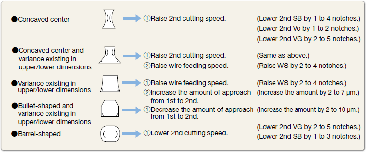
Improvement of cutting precision (For punch shape)
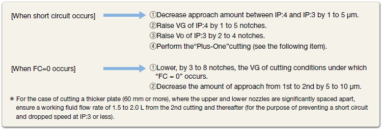
When seams are formed on cutting surface
Tips on finish cutting (points to be checked during cutting)
What should you do if you have a problems and troubleshooting?
Problems and troubleshooting
| Trouble | Phenomenon | Cause | Check item/Solution |
|---|---|---|---|
| 1. Wire breaking | ①Breaking near feed plate |
|
Check the feed plate and replace it periodically. |
|
Clean the feed plate nozzle and check water pressure. | ||
| ②Breaking near wire guide |
|
Perform periodic maintenance. | |
|
Make adjustment for optimal holding force. | ||
|
Reset positioning accuracy. | ||
| ③Breaking when idling |
|
Check wire hooking position. | |
|
Replace or wind off wire. | ||
| ④Breaking immediately after the start of cutting or within 5 mm |
|
Degrease and wash the object subject to cutting, as cutting conditions are very strict. | |
|
Check water pressure of machining liquid. | ||
| Start cutting after plumbing. | |||
| ⑤Breaking after cutting 5 mm or more |
|
Check for positioning error of cutting liquid nozzle and wear. | |
|
Check for dirt of suction opening of cutting liquid supply tank. | ||
|
Check the cutting liquid evacuation route when cutting an object in a complex shape. | ||
|
Replace wire. | ||
|
Check for friction, cracks, and dirt of urethane rubber roller. | ||
| Correct setting error of wire tension. | |||
| 2. Error of cutting accuracy | ①Shaping defect |
|
Adjust pressing force of wire guide and position. |
|
Properly set wire tension. | ||
|
Remove material distortion (stress). | ||
|
Erroneous plumbing of wire. | ||
|
Clean and maintain guide dies and associated components. | ||
| 3. Error of surface accuracy | ①Rough surface |
|
Increase wire transfer speed. |
| ②Wire mark on cutting surface |
|
Increase cutting speed. | |
| ③Unstable cutting speed |
|
Replace ion-exchange resin and stabilize water specific resistance. | |
|
Clean and maintain the wire travel system (i.e., guiding system). | ||
|
Clean, maintain, and check consumption of the power feeder. | ||
|
|||
|
|||
| 4. Faulty cutting speed | ①Increase of cutting speed disabled |
|
Match cutting conditions with those listed in the instruction manual. |
| Check positions and wear of upper and lower nozzles. | |||
| 5. Curl failure | ①Irregular storage of wire within the scrap box (wire running wild to form permanent waves) |
|
Increase applied current by 1 TAP (higher cutting speed). |
|
Replace wire when uneven wear occurs or wear exceeds 1/3 of wire diameter. | ||
|
Consult with maintenance contractor of W-EDM machine. | ||
|
Run wire with pressing force suitable for wire used. | ||
|
Replace the wire with one from a lot having proper straightness. | ||
| 6. Failure of automatic threading (insertion failure) | ①Disabled automatic insertion into guidance and pilot hole |
|
Perform periodical maintenance. |
|
Check minimum lower hole diameter of W-EDM machine. | ||
|
Adjust water pressure valve manually. | ||
|
Perform program checking and centering. | ||
|
Replace the wire with one from a lot having proper straightness. | ||
| 7. Failure of automatic threading (cutting failure) | In case of cutter cutting |
|
Replace wire if a wire mark exists, and check pressing pressure of cutting. |
| ①Poor cutting result |
|
Replace the cutting cutter with a new one. | |
| ②Not inserted into lower hole |
|
Replace the wire with one from a lot having proper straightness. | |
| In case of annealer cutting |
|
Match the wire material and characteristics recommended by the W-EDM maker. | |
| ①Poor cutting result |
|
Enter the diameter of the wire being used. | |
| ②Varied cutting positions |
|
||
| 8. Faulty winding (wire passing beneath another) | ①Wire end passing beneath another |
|
Thoroughly check the wire for passing beneath another after rewinding. |
②Wire passing beneath another occurs in the middle of a spool stroke, even though there is no problem when running |
The customer needs to properly handle the wire end (when setting spool to W-EDM machine). | ||
| 9. Winding failure (loose winding) | ①Loose winding and "playing" wire |
|
Set winding tension for individual wire diameters. |
|
Securely install the machine. | ||
|
Verify the shape and setting state of the spool on the machine. | ||
| 10. Faulty winding (uneven winding) | ①Uneven (i.e., convex and concave) winding in sections close to spool flanges |
|
Adjust traverser and perform periodical checking when rewinding. |
|
Change return control motor. | ||
| Bring traverse pulley as close to winding body diameter as possible. | |||
| Check spool shape. |